
 I Want To


Application Guidelines for a Deck
Application for Permit
To obtain a permit under Subsection 8(1) of the Act, an application can be made using our Cloudpermit electronic permitting service.
Get started with Cloudpermit
Learn more about getting started with the Cloudpermit building permit system and set up your free account.
Additional Permits
The following permits, where applicable, are required to accompany an application for building permit:
- Conservation Authority Approval: To be obtained from the Crowe Valley Conservation Authority.
- Other permits as may be required i.e. ESA, MNR etc.
Required Plans
Drawings, plans and specifications to accompany an application to permit include:
All drawings must be clear, legible, accurate, drawn to scale and conform to the Ontario Building Code.
Site Plan |
|
Foundation Plan |
|
Plans to be provided with a minimum scale where 3/16" equals 1' or 1:75 (metric)
|
Floor Plans |
|
Plans to be provided with a minimum scale where 3/16" equals 1' or 1:75 (metric)
|
Sections and Details |
|
Submissions to be provided with a minimum scale where 1/4" equals 1' or 1:50 (metric)
|
General Notes
- The permit application shall include 2 full size complete sets of prepared fully dimensioned construction drawings. A non-refundable application fee must accompany the application for permit.
- All drawings and specifications are to be project specific.
- Refer to our zoning by-law for setback information, restrictions to location, size, height, etc. (Also see general provisions a top of this page.)
- All drawings are to be drawn to scale. The scale shall be noted on the drawings.
- Do not include presentation graphics (furniture, vehicles, etc.) on construction drawings.
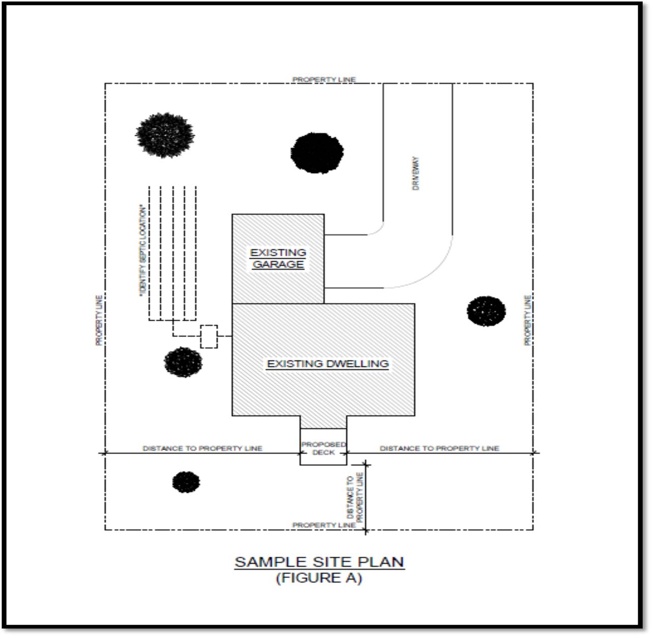
- Where the proposed deck is to be constructed within 1 metre of a required setback or survey monuments are not visible, verification of setback must be provided by an Ontario Land Surveyor prior to footing inspection.
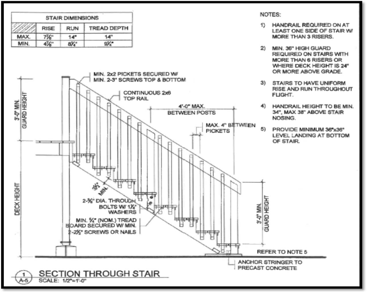
- If the deck surface is more than 2'-0" and less than 5'-11" above finished ground level, a minimum 36" high guard is required. If the deck surface is 5'-11" or more above finished ground level, a minimum 42" high guard is required. Guards are required on stairs where the deck height is 24" or more above finished ground level. No opening in the guard shall exceed 4". Guards shall be designed such that no member, attachment or opening between 5 1/2" and 35" above the deck surface will facilitate climbing.
- Stairs with more than 3 risers require a handrail on at least one side.
- Decks attached to an adjacent structure shall be constructed on foundations that extend to minimum 48" below finished ground level.
- Concrete piers shall be minimum 10" in diameter where the supported post is 6" by 6".
- Where 5/4" decking is proposed, the decking shall be installed perpendicular to the joists where the joists are spaced at 16" o/c. Decking may be installed at an angle of 45 degrees to the deck joist where the deck joists are spaced not more than 12" o/c or 2" by 6" decking is used.
- Required inspections will be conducted within 2 business days from receipt of notice and on assigned days. Required inspections are as follows:
- Footing: After excavation of post holes, prior to the placement of concrete.
- Framing: After framing is complete, prior to the installation of decking and;
- Final: Upon completion of deck, prior to use.
- Doors providing access to the proposed deck shall be secured or blocked to prevent access to deck until final approval for the deck has been granted by the Chief Building Official.
Definitions
- Deck: A raised uncovered platform that is attached to a dwelling. To ensure conformity contact the Building Department to see if a permit is required. Protective guards are required if the walking surface is greater than 24" (610mm) above finished grade.
- Porch: A covered structure (enclosed or unenclosed) that usually forms part of the entrance to a dwelling. Porches require a Building Permit issued by the Building Department. Protective guards are required if the walking surface is greater than 24" (610mm) above finished grade.
- Patio: An uncovered platform at grade level that is constructed of concrete or stone. A patio generally does not require a Building Permit, unless it interferes with an existing structure.
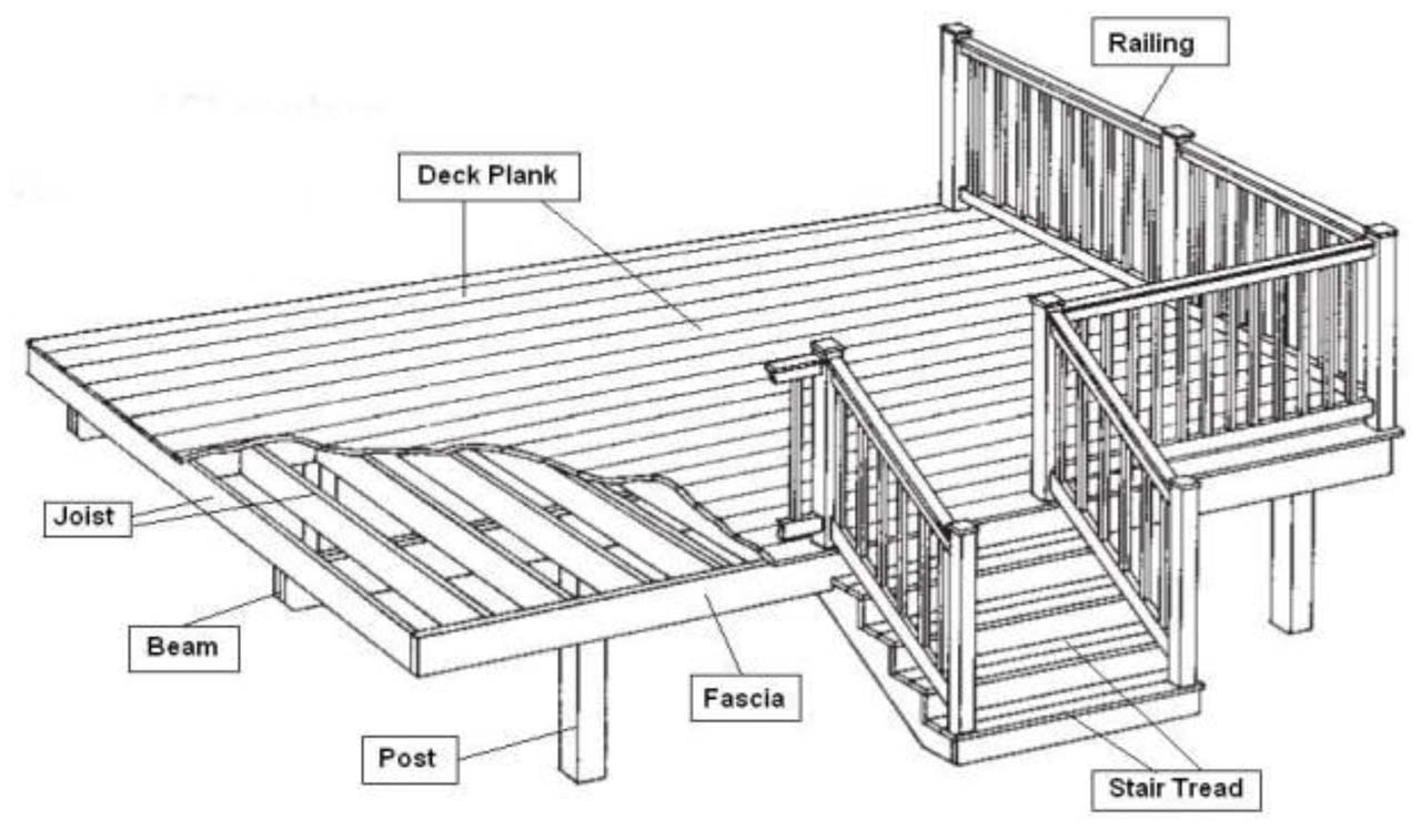
- Joist: Dimensional lumber placed perpendicular to beam that frames the floor system.
- Beam: Laminated dimensional lumber that supports the joists.
- OBC: Refers to the current amended version of the Ontario Building Code.
- Guard: Refers to a protective barrier around decks, porches and the open side of stairs.
Construction Information
Footings and Foundations |
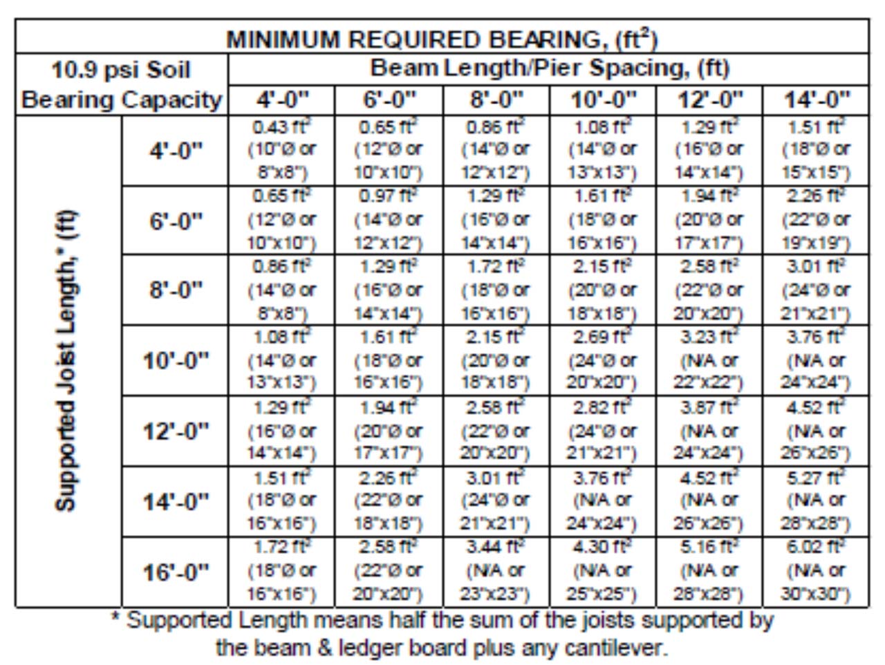
PiersPiers shall not be less than 8” (203 mm) in diameter. Under most circumstances it may be preferable to expand the lower portion of a small pier to achieve the required bearing area rather than use a larger pier. Refer to the table below for minimum footing sizes. Values in table are based on soil bearing capacity of 10.9 psi (75 kPa). Minimum sizes must be double where the solid bearing capacity is affected by a high water table.
ConcreteConcrete piers shall consist of poured concrete with a minimum compressive strength of 2200 psi (15 MPa) after 28 days [OBC 9.3.1.3]. Footing DepthWhere a deck or porch is attached to a dwelling the minimum footing depth shall be 47” (1.2 m). There is no minimum footing depth required for an uncovered deck that is not attached to another structure and is constructed where the finished grade is less than 24” (610 mm) [OBC 9.12.2.2]. HeightPiers shall not extend more than 3 times their width above finished grade [OBC 9.15.2.3 (3)]. ColumnsRound wood columns shall not be less than 7 1/4” Ø (184 mm Ø) or 5 ½” by 5 ½” (140 mm by 140 mm) square [OBC 9.17.4.1(2)]. AnchorageColumns shall be directly fastened to their supports as well as to the framing members for which they are supporting to resist uplift and lateral movement [OBC 9.23.6.2]. |
Ledgers, Joists and Beams |
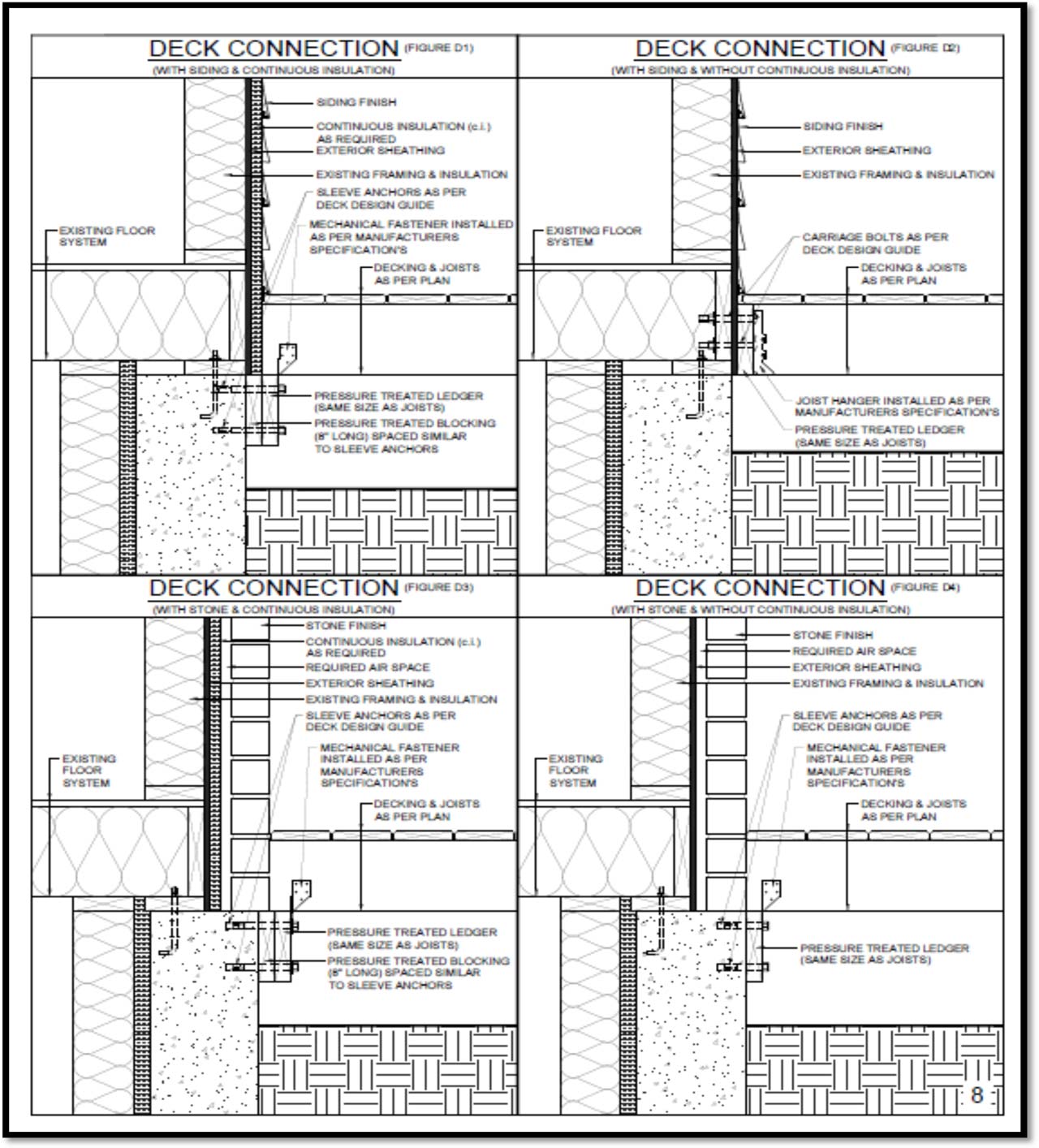
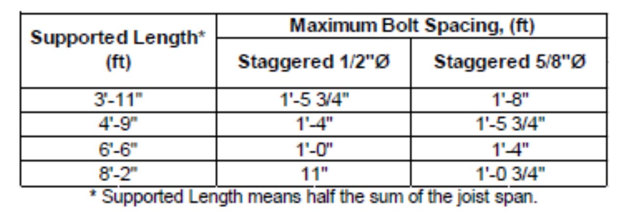
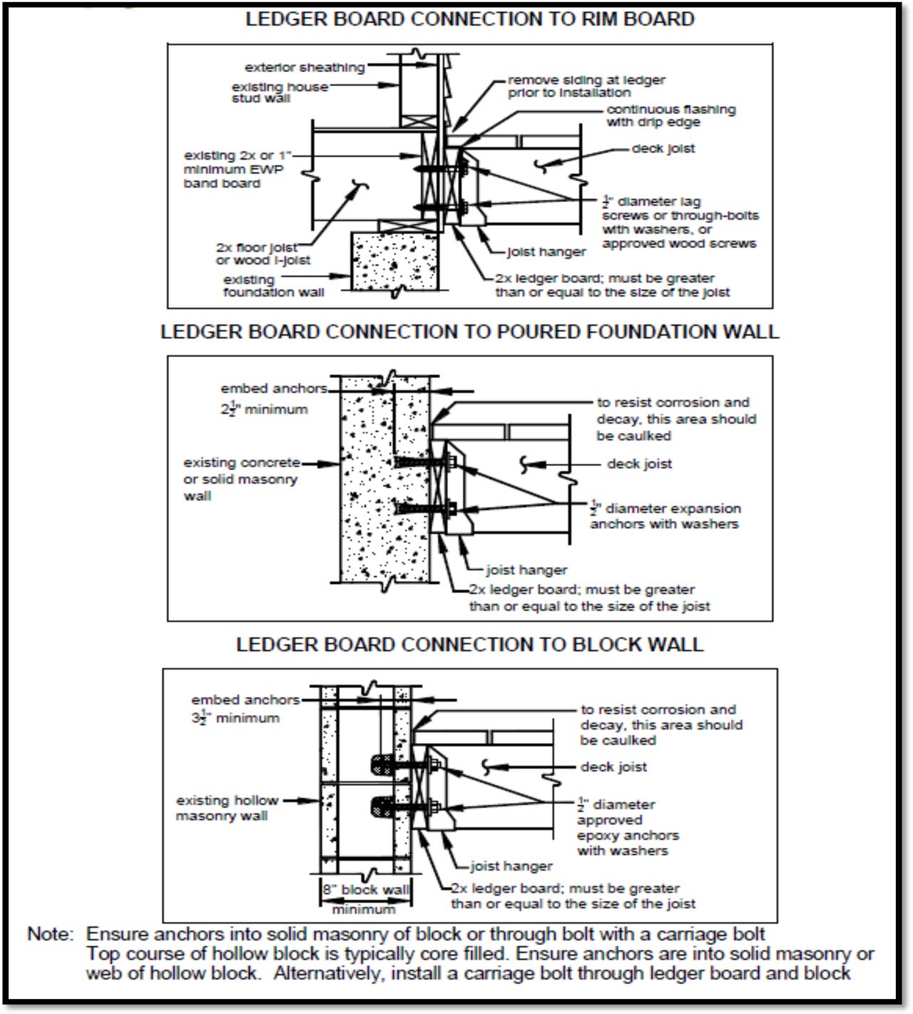
Ledger BoardLedger boards shall consist of the same nominal sized lumber as the deck joist and contain joist hangers to support the deck joists. These hangers shall be coated to prevent corrosion and installed as per manufacturer’s specifications. Ledger AnchorageAnchorage for ledger boards shall consist of expandable sleeve anchors for solid concrete or concrete filled masonry or carriage bolts with nuts and washers into suitable structural lumber. In all cases they shall be embedded minimum 4” (100 mm). Refer to the table below for size and spacing. See diagrams below for connection methods.
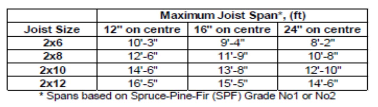
JoistsJoists may be supported on either the top of a built-up beam or joist hanger coated to prevent corrosion and installed as per the manufacturer’s specifications. At no time shall the minimum bearing of the joists be less than 1 ½” (38 mm). Each joist bearing on a built up beam must be mechanically fastened to the beam with two (2) galvanized framing nails 3 ¼ (82 mm) in length. Refer to the table below for maximum size and spacing of joists.
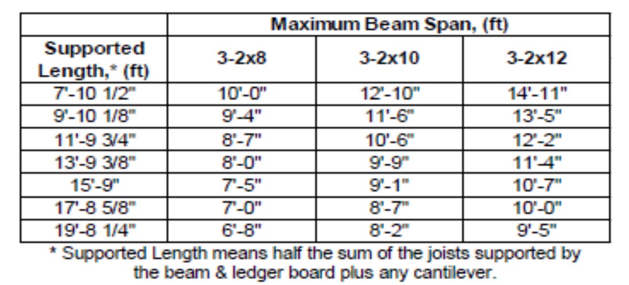
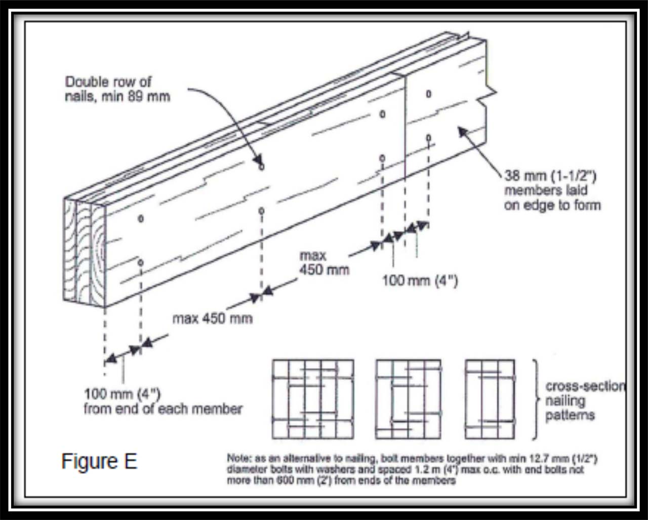
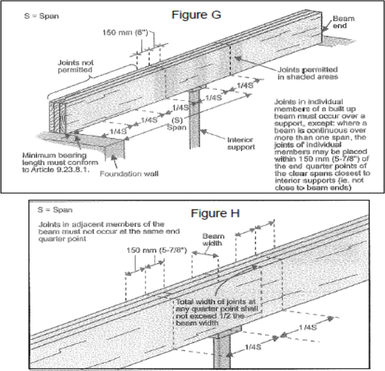
BeamsBuilt-up beams shall have not less than 3 ½” (89 mm) of bearing and be fully supported over their width [OBC 9.23.8.1.]. Where individual members are butted together to form a joist, the joint must occur over the support. Built-up beams shall be nailed together with a double row of galvanized framing nails not less than 3 ½” (89 mm) in length. Spacing shall not be more than 18” (450 mm) apart and not more than 4” (100 mm) from the end [OBC 9.23.8.3.(7)]. Refer to the table below for maximum built-up beam size and length. See Figure E below for nailing patterns, etc.
Cantilever2” by 8” (38 mm by 184 mm) joists supporting roof loads shall not cantilever more than 16” (400 mm) beyond their supports. Joists sizes larger than 2” by 8” shall not cantilever more than 25” (600 mm) beyond their BlockingWhere joist spans are greater than 6’-11” (2.1 m) cross bridging or solid blocking shall be provided at mid span. Cross bridging or solid blocking shall be:
Bridging or blocking shall be fastened with two (2) galvanized framing nails 2 ¼” (57 mm) in length at each end. |
Decking and Fasteners |
DeckingPlank type decking less than or equal to 7 ¼” (184 mm) wide shall be fastened with two (2) galvanized framing nails 2” (51 mm) in length or two (2) 1 ¾” (45 mm) coated screws. Decking shall be at least 11/16” (17 mm) thick when placed on joists spaced 16” (400 mm) on centre or less and 3/4” (19 mm) thick when placed on joists spaced 24” (600 mm) on centre. FastenersMust be treated or coated to prevent corrosion. Screws may be used in lieu of nails so long as they provide equal strength. |
Stairs, Railings and Guards |
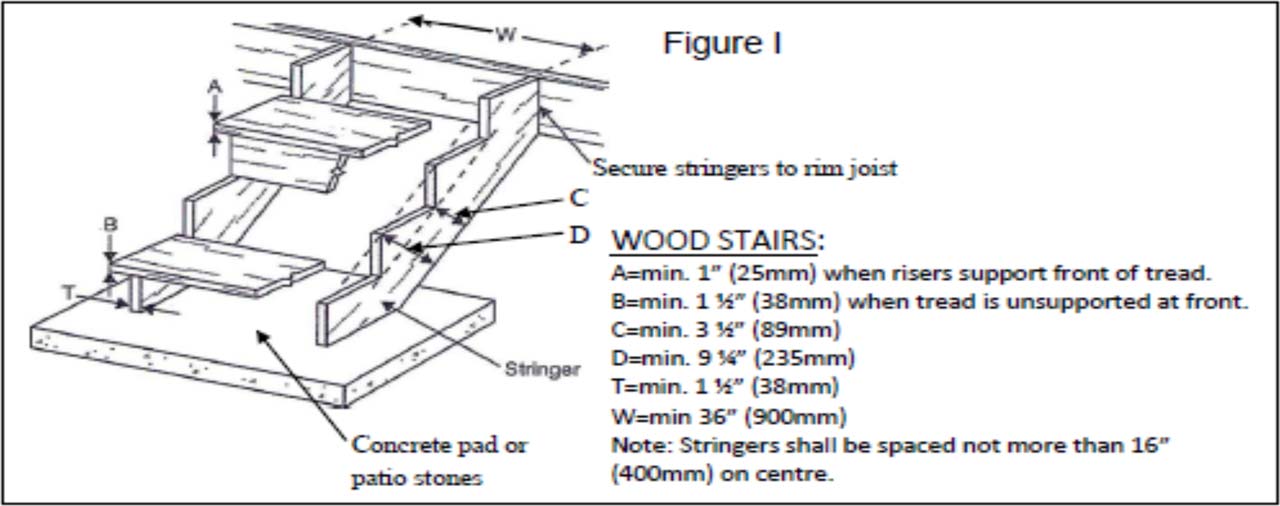
Stairs
RailingsRailings must conform to Supplementary Standard SB-7 of the Ontario Building Code. GuardsExterior guards shall not be less than 36” (900 mm) high where the walking surface served by the guard is not more than 5'-11” (1.8 m) above finished grade otherwise the guard can not be less than 42” (1070 mm) high. If a bench is incorporated into the guard than the required height is measured from the bench surface [OBC9.8.8.3]. The opening in the guard balusters shall be the size that will prevent the passage of a spherical object having a diameter of 4” (100 mm) [OBC 9.8.8.5]. Guards shall be designed so that no member, attachment or opening will facilitate climbing [OBC 9.8.8.6]. Please refer to the Supplementary Standard SB-7 of the Ontario Building Code for more details. |
Deck Connection Methods |
 |
Sample Plans
All measurements must be accurate.
Sample Site Plan for a Deck |
 |
Sample Plan and Section Drawing |
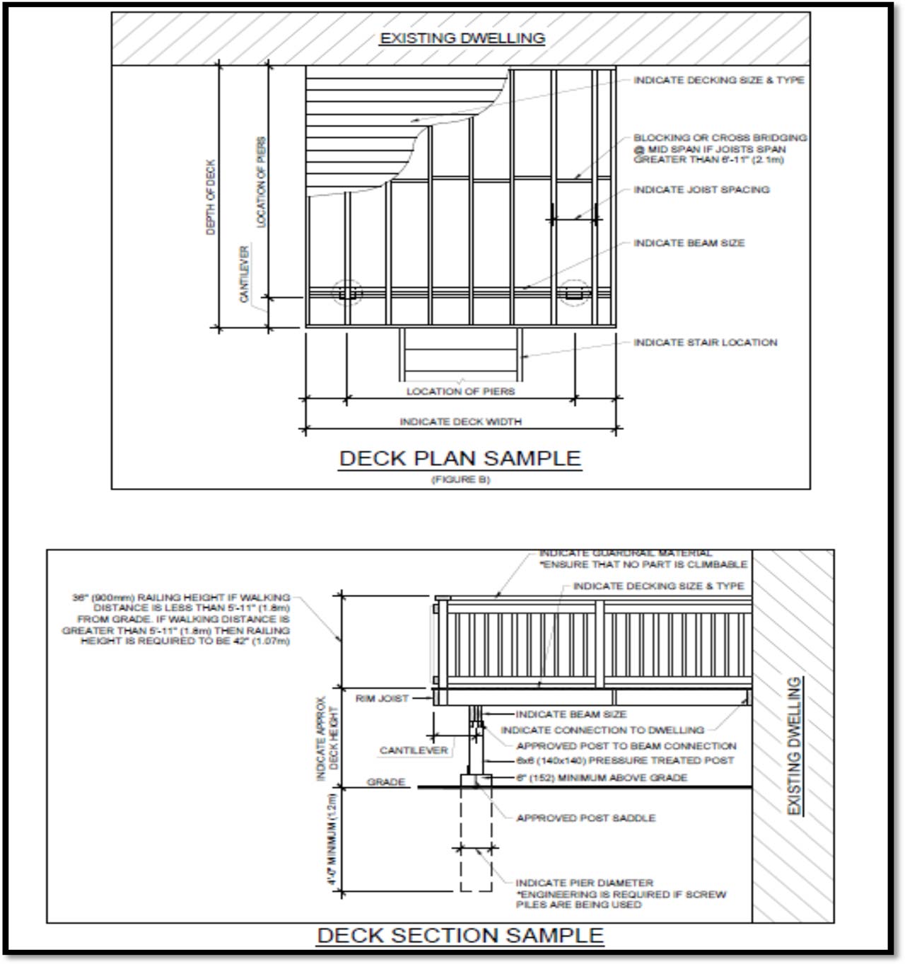 |
Supplementary Standard SB-7 Excerpts
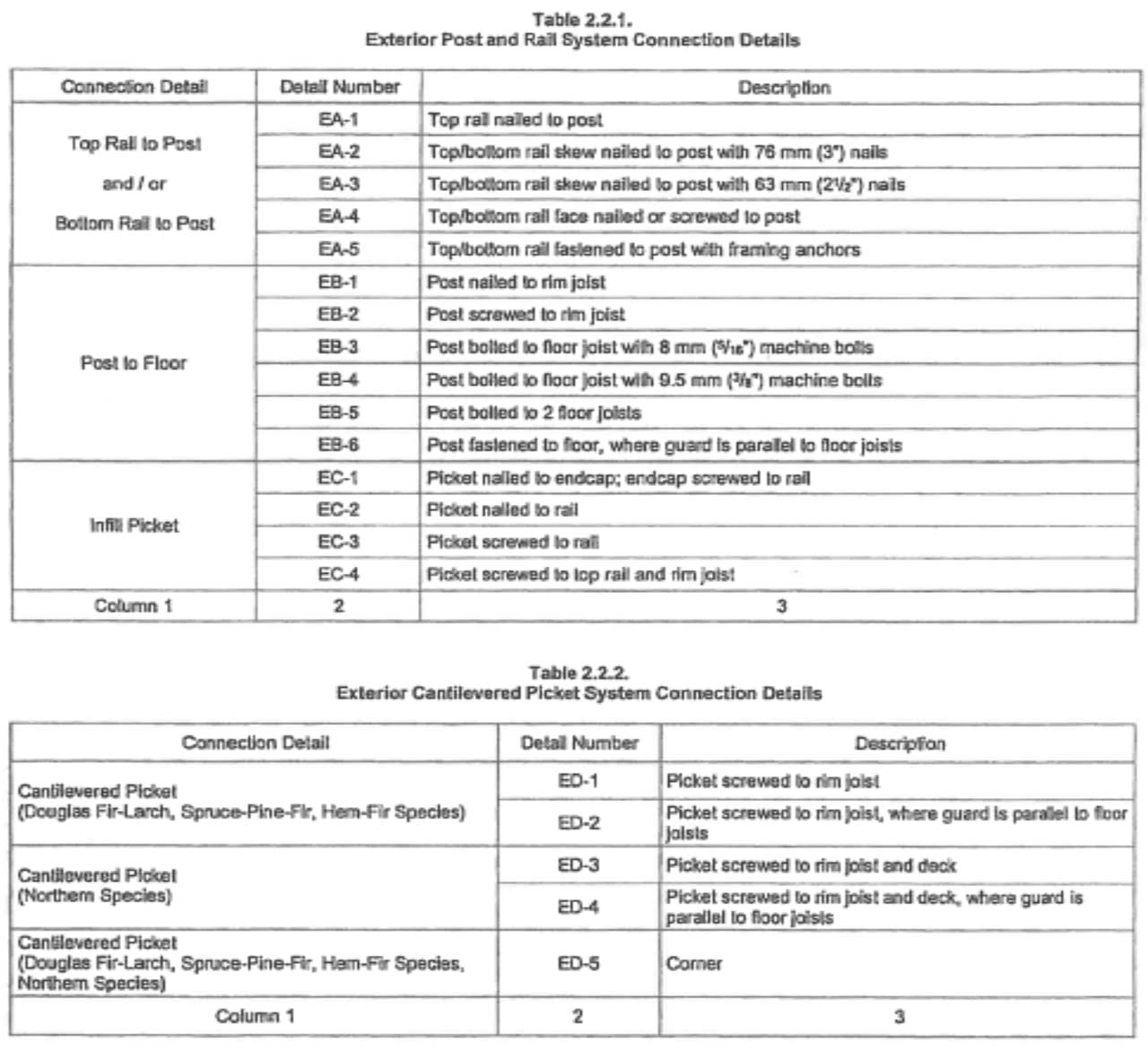
Connection Detail Tables 2.2.1 and 2.2.2 |
 |
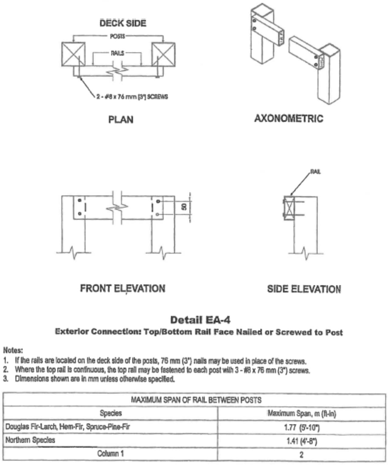
Detail EA-4: Top/Bottom Rail Face Nailed or Screwed to Post |
 |
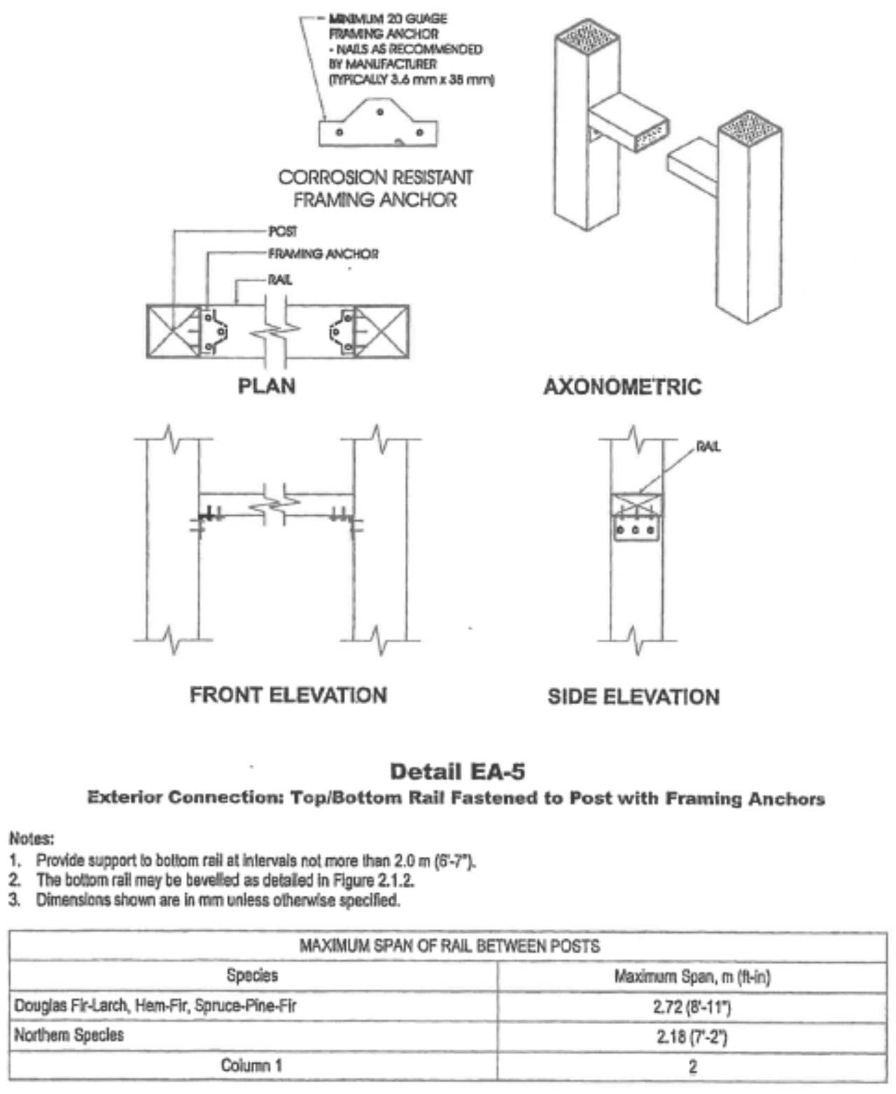
Detail EA-5: Top/Bottom Rail Fastened to Post with Framing Anchors |
 |
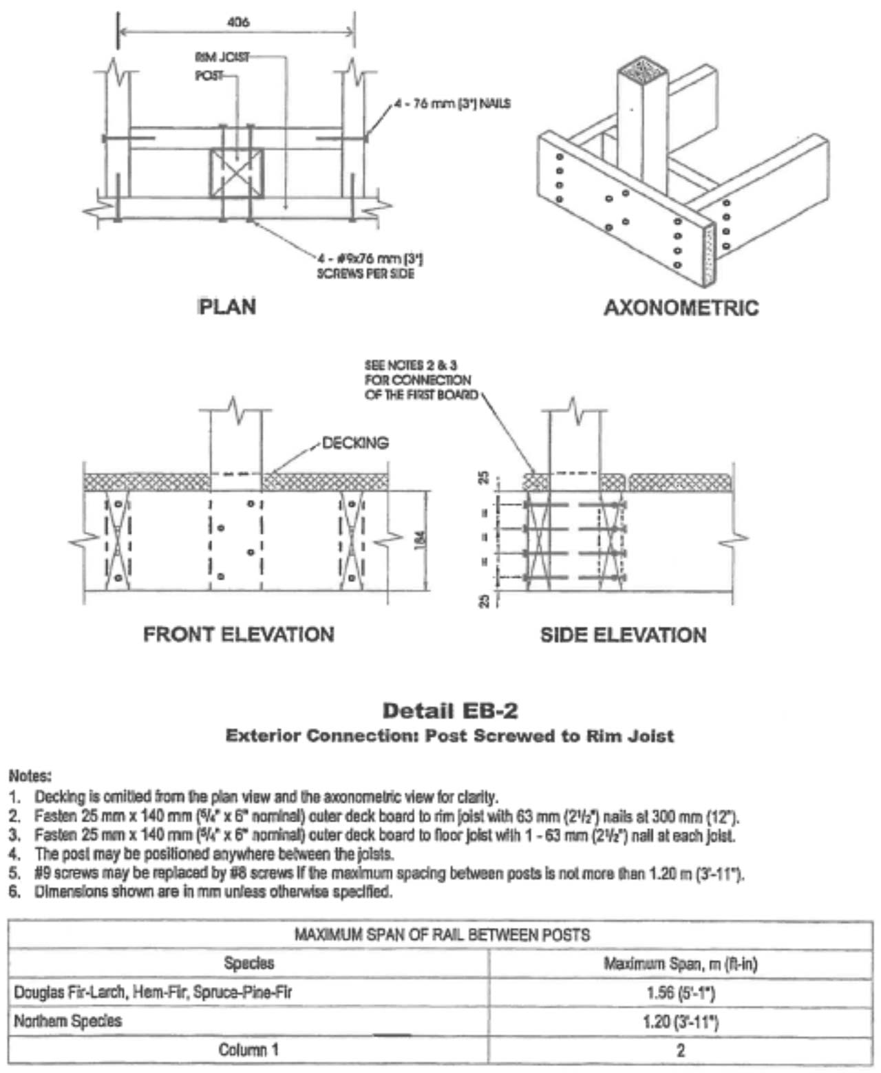
Detail EB-2: Post Screwed to Rim Joist |
 |
Detail EB-4: Post Bolted to Floor Joist with 9.5 mm (3/8") Bolts |
 |
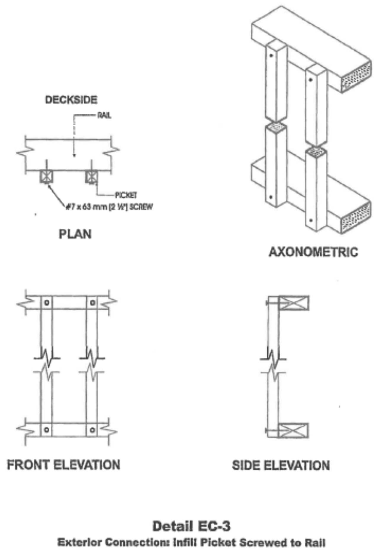
Detail EC-3: Infill Picket Screwed to Rail |
 |
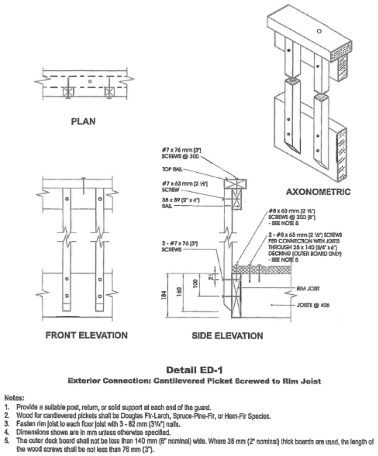
Detail ED-1: Cantilevered Picket Screwed to Rim Joist |
 |
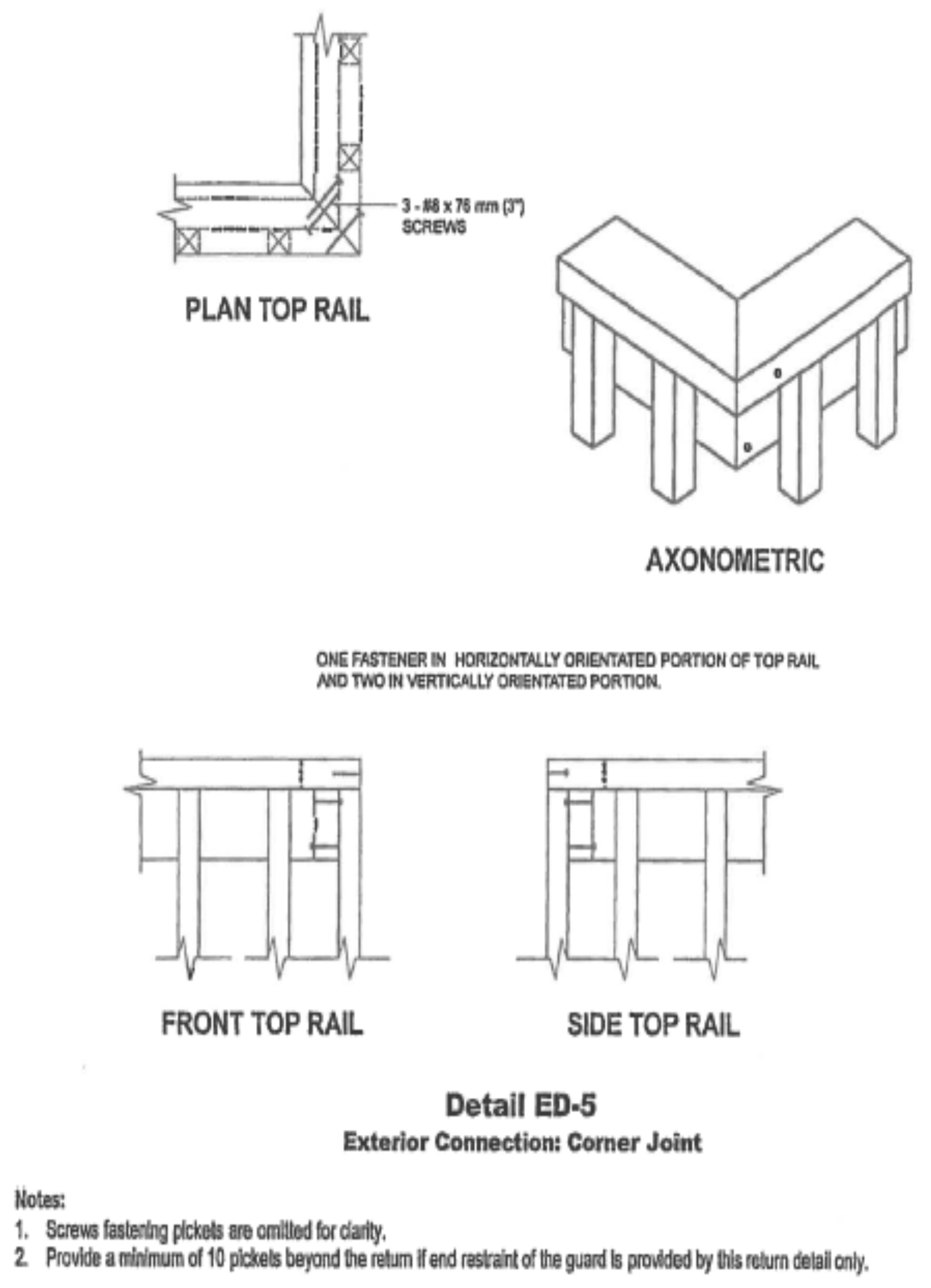
Detail ED-5: Corner Joint |
 |
Contact Us
 Subscribe to this Page